1. Introduction
1.1. writing purpose
This document describes the use of CubieBoard6 Linux system.
1.2. Application scope
CubieBoard6 Linux system.
2. Ethernet
2.1. networking
All cubieboard development board Ethernet is the default setting for the DHCP mode to dynamically access IP. To ensure that the router or switch is no problem, just insert the network line to get IP address can be on the Internet. In some cases you may need to enter the following command:
$sudo dhclient eth0
2.2. static IP
The following steps to set static
$sudo vi /etc/network/interfaces
Modified file:
auto lo eth0 allow-hotplug eth0 iface lo inet loopback iface eth0 inet static address 192.168.1.X gateway 192.168.1.1 netmask 255.255.255.0 network 192.168.1.0 broadcast 192.168.1.255
The bold part should be set according to the local area network. "X" Changed to the required IP to ensure that IP does not conflict . Save exit and restart the system
3. display
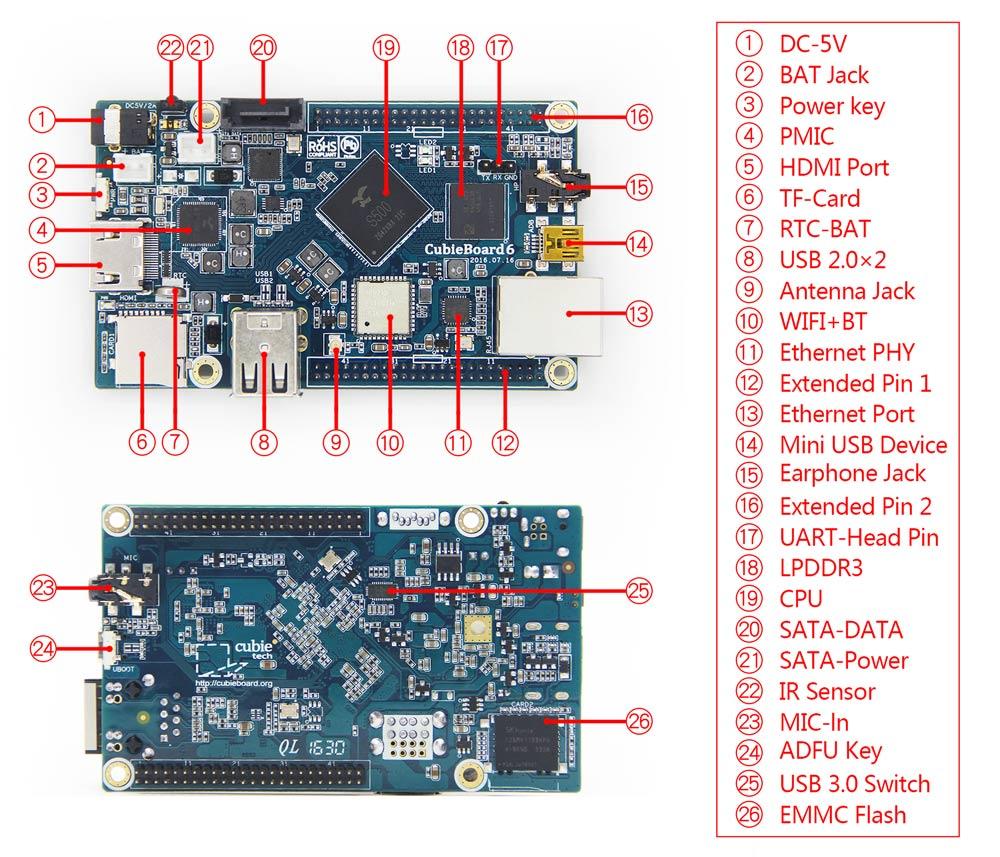
Cubieboard6 default is HDMI display. Before power on the board and the display is connected to the board, the system will be adaptive EDID configuration resolution. If the system starts to read the display of the EDID, and the display can support 1080p, then display 1080p, or display 720P .
4. TF CARD
4.1. memory card
To use the new 8G TF CARD as an example. If you use the DESKTOP system, and the system supports card format, the system will automatically mount card, ask whether access to files, similar to the WINDOWS operation
Manually mount: 1) Find device node After the TF CARD is inserted into the slot, the following commands are entered in the board system terminal:
$ sudo fdisk -l

The red box for TF card information, which indicates that the system has to identify TF card devices, "/dev/mmcblk1" is a device node . Out of the box for EMMC information, you can see the EMMC is 8G, and there are several partitions.
2) If you need to format, enter the command in the terminal
$ sudo mkfs.vfat -I /dev/mmcblk1
Card format for VFAT format, this format can be identified by the WINDOWS system to facilitate the operation of the data . Format, the previous data will disappear, the card has been used to skip this section.If there is no special needs, you can not go to the partition.
3)Mount the device
$ mount /dev/mmcblk1 /mnt
$ df -h
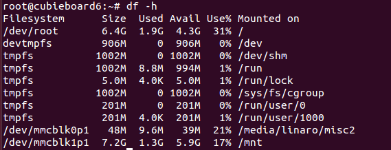
If there is no error, that can be mounted successfully, the device to read and write data.
5. USB
The main use of the USB device has a storage disk, mouse keyboard, USB camera.
5.1. storage disk
Refer to the previous chapter TF CARD description, generally do not need to format the disk.
5.2. mouse keyboard
Cubieboard6 supports most HID devices, mouse, keyboard.
5.3. USB camera
Access to the display using the HDMI line, the USB camera into the cubieboard6 development board USB. Open the terminal, the installation of the mplayer2 tool can open the camera
Download mplayer2 tools
$sudo apt-get install mplayer
Open USB camera
$mplayer -vo x11 tv://
6. SATA
Cubieboard6 is USB3.0 through the SATA conversion chip to turn out the SATA interface.

7. Audio
7.1. earphone
Default sound output from headphone. You can hear the sound by running the following command to test the audio, but also can directly use the player to play test audio.
Audio test command:
$ speaker-test -t wav -c2
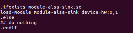
7.2. HDMI
To switch to HDMI audio output, modify configuration:
$ vi /etc/pulse/default.pa
find this information:
load-module module-alsa-sink device=hw:0,0
change to the following:
load-module module-alsa-sink device=hw:0,1
8. MIC
Cubieboard6 support with MIC headset recording. Insert four stage headphones into the headphone socket or insert the MIC line of the three stage headphones into the MIC slot on the bottom of the board。
Recording command:
$ arecord -vv -t wav -f S16_LE -c 2 -r 24000 ./record.wav
Play recorded sound:
$ aplay record.wav
9. Wireless network
9.1. wifi connection
Desktop version of the system has WIFI connection tool, click on the lower right corner of the desktop icon tool to achieve quick connection.
Note: before connecting wifi, connect the antenna to increase the signal.
The following is the command line configuration wifi method.
1.) Load wifi driver
The default is that the wifi driver “ wlan_bcmdhd”, “ bcmdhd_prealloc” and “rfkill_actions_bcmdhd” have been loaded automatically.
If you want to manually load the wifi driver command :
$sudo modprobe wlan_bcmdhd bcmdhd_prealloc rfkill_actions_bcmdhd
2.) Be sure to find hot spots and see signal strength
Common command:
$iwlist wlan0 scan
$iw wlan0 scan
$wpa_cli -i wlan0 -p /var/run/wpa_supplicant/ scan
$wpa_cli -i wlan0 -p /var/run/wpa_supplicant/ scan_results
3.) Modify configuration**
$sudo vi /etc/network/interfaces
Add the following:
auto wlan0 iface wlan0 inet dhcp pre-up wpa_supplicant -B -i wlan0 -c/etc/wpa_supplicant/wpa_supplicant.conf pre-down killall -q wpa_supplicant
Modify another configuration file:
$sudo vi /etc/wpa_supplicant/wpa_supplicant.conf
Add the following:
ap_scan=1 network={ ssid="you-ssid-here" psk="you-passwd-here" }
your-ssid-here mean :WiFi hotspot name
your-passwd-here mean:Password
Note: if the wpa_supplicant.conf file is not, you can create a new
4.) Reboot system. If you restart, you can not get IP, restart the network card
$sudo ifconfig wlan0 down
$sudo ifconfig wlan0 up
$sudo /etc/init.d/networking restart
10.bluetooth
10.1.GUI connect
1.)Bluetooth firmware
$ sudo start-bt.sh &

The final print appears as shown above, indicating the success of the Bluetooth firmware upload 2.)Open the Bluetooth blueMan tool, as shown in the figure
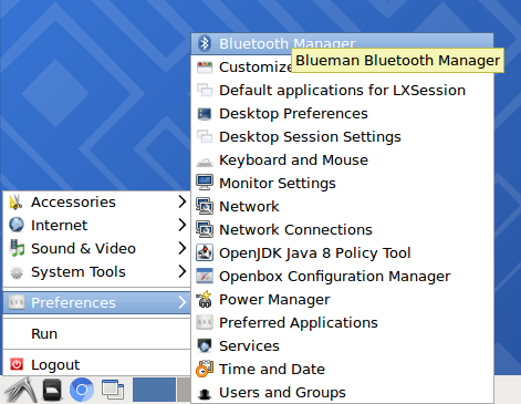
3.) Bluetooth tool opens successfully, click Search to search for Bluetooth devices, pairing.
4.) After the match is successful, click on the yellow star, set the device to be trusted .
5.) Click "Send File" to start sending or receiving files from other devices.
11.KODI player
KODI player supports hard decoding mainstream codec video and package format 1080P video.
$cp /usr/local/share/applications/kodi.desktop
/usr/share/applications/kodi.desktop Right click the video file, select the KODI application to open, you can play directly. Or enter a command play in the terminal:
$kodi test.mp4
You can press "\" button to do full screen and window display switch.
12.keys
12.1.PWR key
Boot state, long press the PWR key 6S is a hardware restart. Shutdown state, long press the PWR key 2S, automatic boot.
12.2.ADFU key
When you want to burn the firmware, long press into the burning mode.
13.IR
The default is to load the IR module atc260x_irkeypad.
The success of the remote user code configuration, driver can receive physical key.
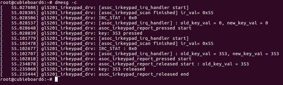 As shown in the figure, the key press for physical mapping of 0x55, its value is 353. These need to be configured in the DTS file
DESKTOP remote control application 1.) Find infrared counterpart “input event”
$ cat /proc/bus/input/devices | grep irkeypad
From the print you can see the corresponding “input event” is “ event1”
Enter the desktop, open the terminal, enter:
$sudo keybinder /dev/input/event1
2.) Use the remote control to press a key, as shown below :
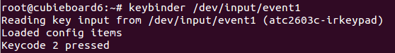 As can be seen from the figure, press the key mapping value is 2".
Know the remote control keys, can use it to open the application on the desktop, such as Notepad application:
As can be seen from the figure, press the key mapping value is 2".
Know the remote control keys, can use it to open the application on the desktop, such as Notepad application:
echo "2,gnome-text-editor" >> /etc/keybinder.conf
"2" is the key, "gnome-text-editor" is to open the application,You can also open the "/etc/keybinder.conf" to modify, add a number of buttons corresponding procedures. Then press the corresponding button to open the application.
14.battery
Connect the lithium battery, and then connect the DC power, the following commands can be used to see: the current battery current, voltage, battery capacity (100 is full)
$cat /sys/class/power_supply/battery/voltage_now
$cat /sys/class/power_supply/battery/current_now
$cat /sys/class/power_supply/battery/capacity
15.LED
15.1.LED1
Led1 is a custom lamp Bright LED1:
$echo default-on > /sys/class/leds/led1-GPIOB9/trigger
Put out LED1 :
$echo none > /sys/class/leds/led1-GPIOB9/trigger
15.2.LED2
LED2 is defined as "heartbeat", indicating that the system is running. If the LED2 appears bright or extinguished, the system may have crashed.
$cat /sys/class/leds/led2-GPIOB8/trigger
none battery-charging-or-full battery-charging battery-full battery-charging-blink-full- solid ac-online usb-online mmc0 mmc1 mmc2 timer [heartbeat] gpio default-on cpu0 cpu1 cpu2 cpu3
Put out LED1:
$echo none > /sys/class/leds/led2-GPIOB8/trigger
16.RTC
If there is a network, the system time is automatically updated. Or manually update the system time:
$ntpdate-debian
If there is no network, set the time manually
$date -s 10:20:30
$date -s 20170102
RTC battery to ensure that at least 2.5V voltage, to ensure that the system time is correct, at least restart or shutdown once, the system will automatically write time to RTC .After the battery as long as the case of electricity, even if the DC power down, but also to maintain the time update. After network is broken, the system time is updated according to the hardware time.
Common commands are as follows: View hardware time
$ hwclock –show
Set hardware time
$hwclock --set --date="11/11/14 11:11"
Hardware clock synchronization with system clock
$hwclock –hctosys
System clock and hardware clock synchronization
$hwclock –systohc
17.extended PIN
Cubieboard6 extended PIN function definition:

